
My Cart
0 items
Genuine Automation Parts | Worldwide Express Delivery | 12-Month Warranty — [GET A QUOTE]

The YOKOGAWA SAI143-H63 S4 is a high-density analog input module designed for signal acquisition in CENTUM VP and other distributed control system (DCS) architectures. It provides precise conversion of field-level...
Availability: In stock
Reliable Worldwide Delivery
30-Day Money-Back Guarantee
Need more details? Read our fullShipping PolicyandRefund Policy.
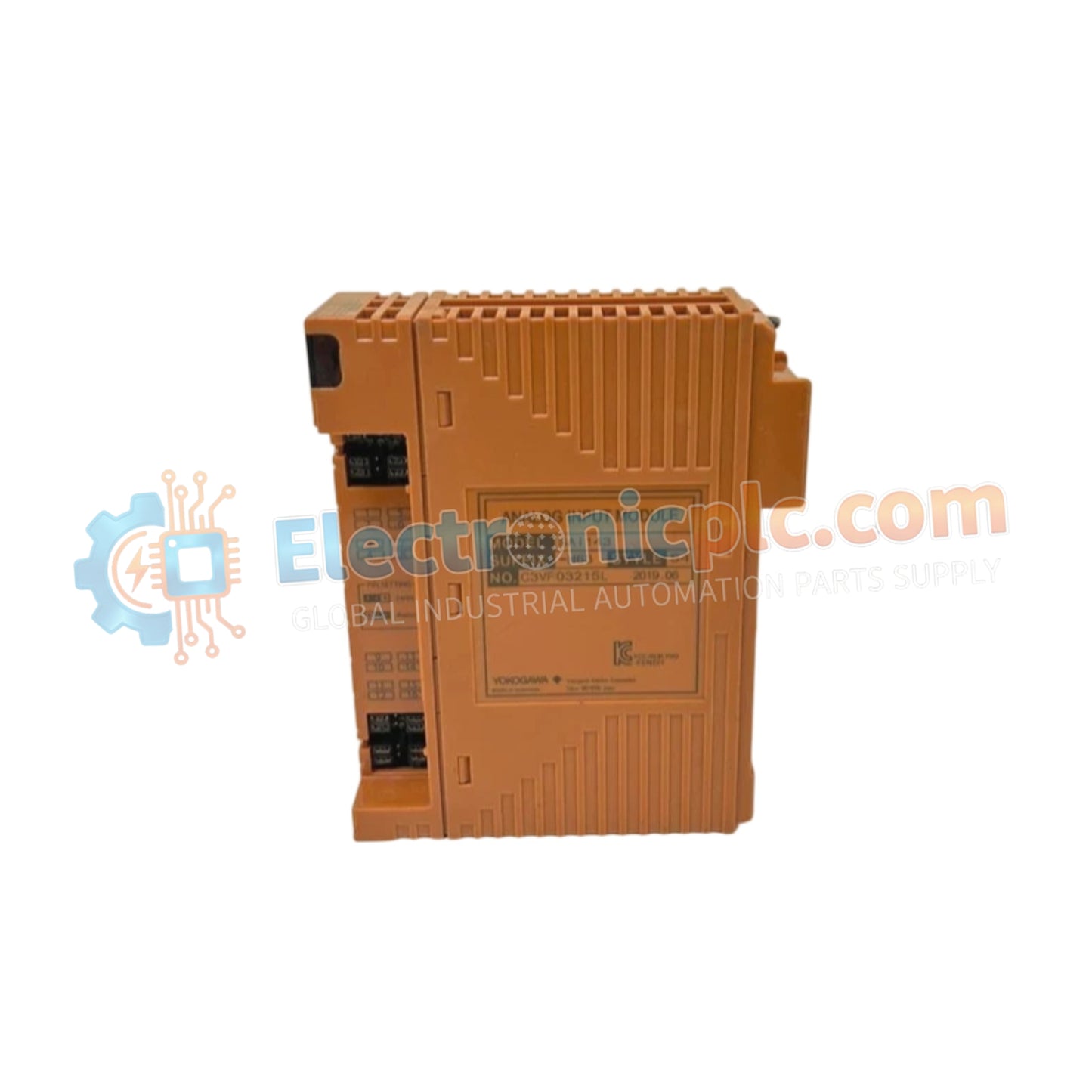
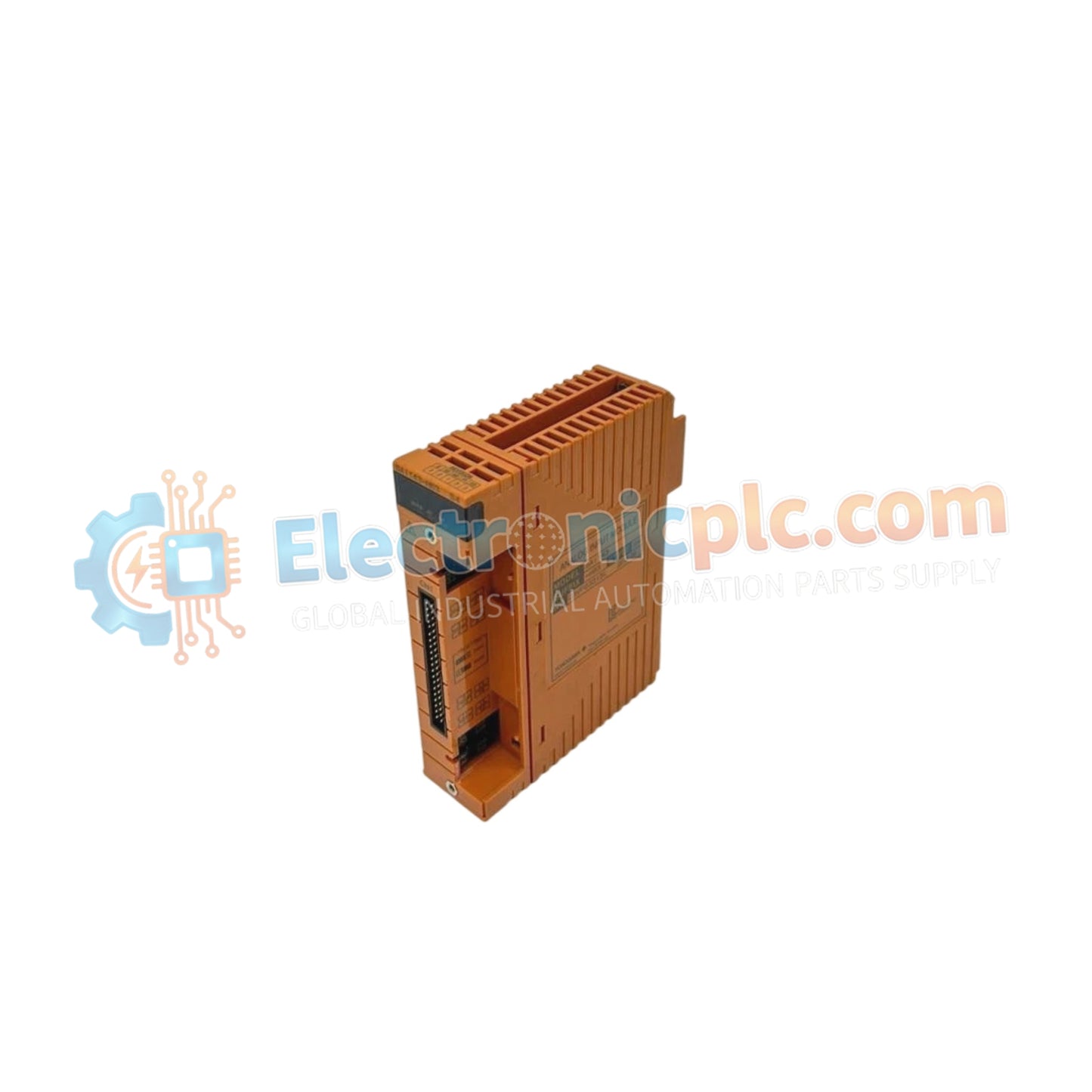
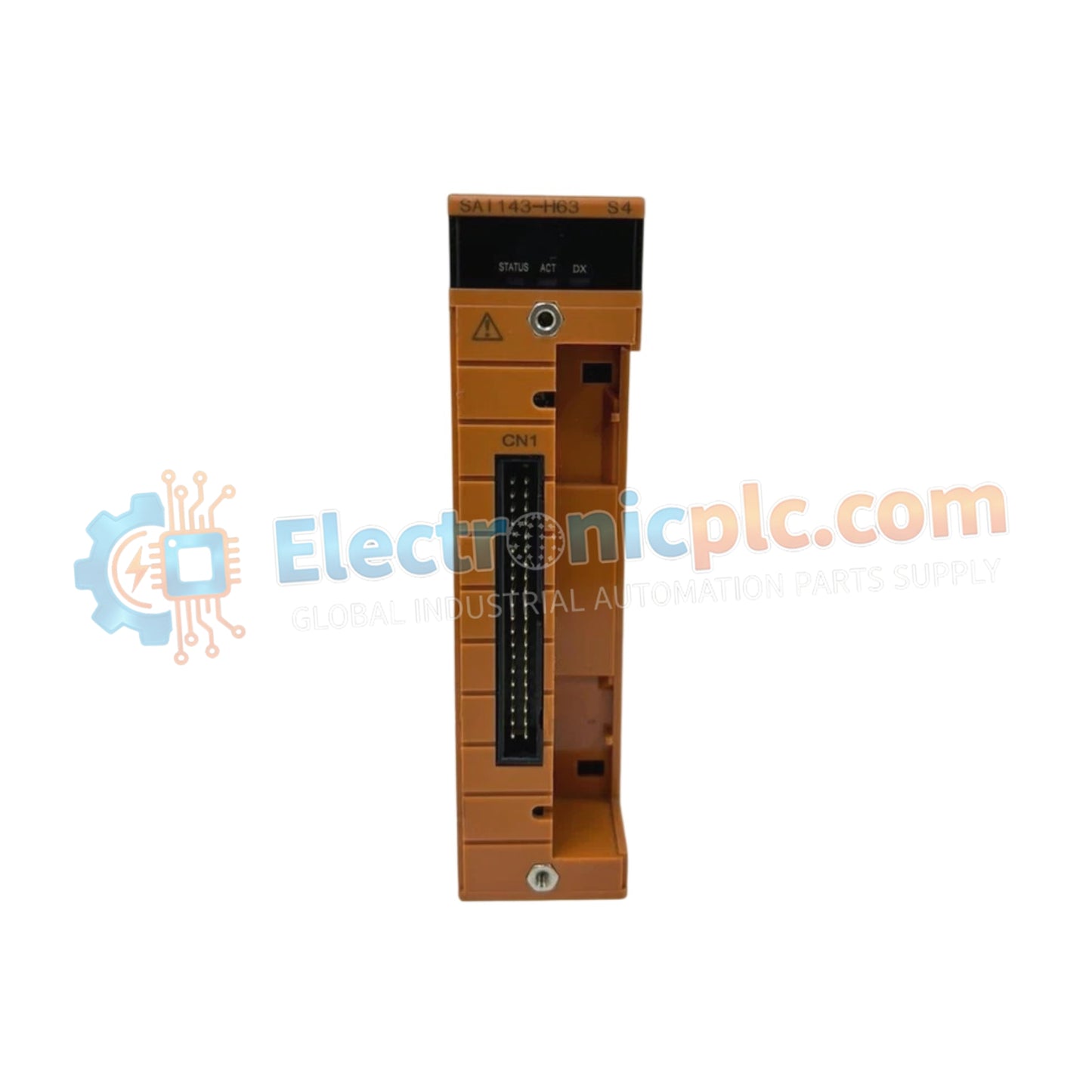
The YOKOGAWA SAI143-H63 S4 is a high-density analog input module designed for signal acquisition in CENTUM VP and other distributed control system (DCS) architectures. It provides precise conversion of field-level analog signals into digital data for processing and monitoring.
| Parameter | Specification |
|---|---|
| Model | SAI143-H63 S4 |
| Brand | YOKOGAWA |
| Origin | Japan |
| Weight | 0.3 kg |
| Dimensions | 12.7 cm x 22.9 cm x 17.8 cm |
| Operating Temp | 0 deg C to 50 deg C |
| Function | Analog Input Module |
| Compatibility | CENTUM VP / Distributed Control Systems |
The SAI143-H63 S4 is engineered to support standard industrial analog signals (typically 4–20 mA or 1–5 V DC), facilitating the integration of various sensors and transmitters into the DCS. The module features galvanically isolated input channels, which significantly reduces the influence of common-mode noise and ground loops in industrial environments. This level of isolation is crucial for maintaining measurement accuracy and protecting the controller hardware from transient voltage spikes originating from field instrumentation.
Q: Can this module be configured for different input ranges?
A: Yes, range configuration and channel-specific settings are managed through the DCS engineering workstation. The module handles scaling and linearization internally, allowing for seamless integration of various process variables.
Q: Is the SAI143-H63 S4 capable of detecting open-circuit failures?
A: Yes, the module includes diagnostic capabilities that monitor the input current loop. If the current falls below the minimum threshold (e.g., < 3.6 mA for a 4–20 mA loop), the module reports an open-circuit fault to the controller, allowing for rapid maintenance response.


