Skip to product information
1 of 3

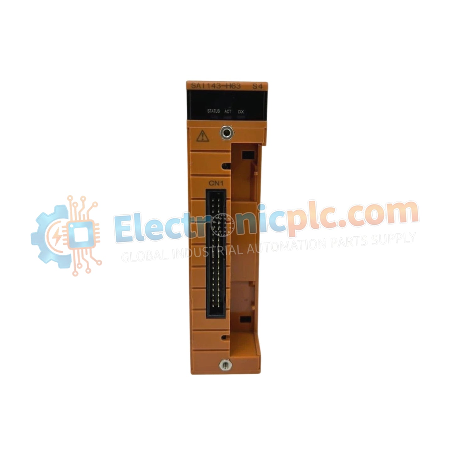
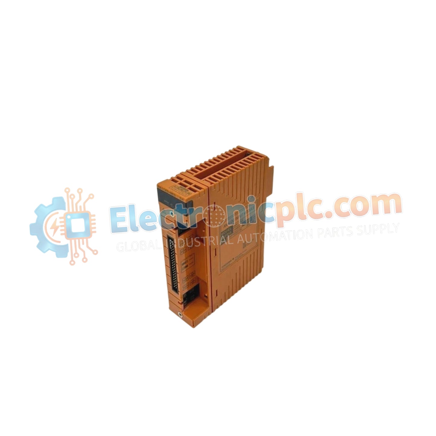
YOKOGAWA SAI143-S53/A4S00 Analog Input Module

YOKOGAWA SAI143-S53/A4S00 Analog Input Module

Configured for high-density signal acquisition in SIS platforms, the YOKOGAWA SAI143-S53/A4S00 (SAI143-S53/A4S00 Analog Input Module) provides direct electrical current measurement and transmitter power distribution for industrial safety loops.

Suffix Breakdown...

21 people are viewing this right now

AvailabilityIn stock

SKU: SAI143-S53/A4S00
Vendor: Yokogawa
Related Series:

Shipping & Returns

Reliable Worldwide Delivery

  • Carriers: Shipped via DHL, FedEx, UPS, or USPS.
  • Dispatch: Orders processed in 1-2 business days and dispatched within 3-5 business days.
  • Tracking: Full tracking details provided via email upon shipment.

30-Day Money-Back Guarantee

  • Guarantee: 30-day return window for in-stock, factory-sealed products.
  • Condition: Items must be unopened, unused, and in original packaging.
  • Authenticity: We guarantee 100% original and authentic hardware.

Need more details? Read our fullShipping PolicyandRefund Policy.

Authenticity & Warranty

  • Genuine Guarantee: We supply only 100% original, brand-new, and factory-sealed industrial automation parts.
  • Full Coverage: Every component is backed by a 12-month comprehensive warranty from the date of purchase.
  • Traceability: All products come with original factory documentation and accessories for full industrial compliance.

Technical Support & Sourcing

  • Expert Assistance: Our technical team provides free consultation to help you verify compatibility for DCS and PLC systems.
  • Rare Part Sourcing: Specializing in obsolete and hard-to-find components from Allen-Bradley, Siemens, ABB, HIMA, and more.
  • Bulk Inquiries: Contact us at pambo@5gplc.com for volume pricing or customized project quotes.
View full product details

Configured for high-density signal acquisition in SIS platforms, the YOKOGAWA SAI143-S53/A4S00 (SAI143-S53/A4S00 Analog Input Module) provides direct electrical current measurement and transmitter power distribution for industrial safety loops.

Suffix Breakdown & Model Matrix

  • SAI143-S53: Base model for 16-channel analog input with standard I/O processing.
  • /A4S00: Specifies the specific terminal interface and electrical protection configuration for safety-rated applications.

Hardware Specifications

Parameter Specification
Model SAI143-S53/A4S00
Brand YOKOGAWA
Origin Japan
Weight 0.39kg
Dimensions Not specified
Operating Temp Not specified
Power Consumption Not specified
Channels 16
Input Range 4-20 mA (0-25 mA permissible)
Accuracy +/- 16 uA
Update Period 40 ms

Safety Instrumented System Signal Integrity

The SAI143-S53/A4S00 utilizes module-level galvanic isolation to ensure that signal faults in one loop do not propagate to the remaining channels, a critical requirement for high-availability SIS architectures. The input circuitry is designed to manage 4-20 mA HART loop protocol signals, providing the necessary DC bias to power two-wire transmitters while maintaining a 250 Ohm input impedance during active operation. This design facilitates precise measurement of process variables while ensuring robust electrical protection against transients common in large-scale industrial instrumentation networks.

Frequently Asked Questions

Q: Does this module support redundant SIS configurations?

A: Yes, the 16-channel architecture allows for integration into redundant SIS setups; however, external configuration and voting logic must be handled by the safety processor to ensure the required fail-safe state execution.

Q: Why does the input impedance change from 250 Ohm to 500 kOhm when power is removed?

A: The high impedance in the power-off state prevents the module from loading the signal loop when the internal electronics are inactive, preventing potential signal degradation in multi-dropped instrumentation circuits.

Field Installation Guidelines

  • Verify that the loop power supply voltage (16.15 V to 26.4 V) is correctly calibrated to the specific transmitter load to ensure the loop remains within the operational 4-20 mA range.
  • Use shielded, twisted-pair cables for all field inputs; ensure shields are grounded at the junction box or cabinet entry point to minimize electromagnetic interference (EMI).
  • Ensure that the total current draw does not exceed the capacity of the transmitter power supply, particularly when all 16 channels are active and powering transmitters simultaneously.
  • Periodically check for signal drift, particularly if the cabinet environment temperature fluctuates, noting that the drift coefficient is +/- 16 uA per 10 deg C.
  • Secure the terminal blocks firmly to the module header to ensure the integrity of the 16-channel signal path under vibration.