
My Cart
0 items
Genuine Automation Parts | Worldwide Express Delivery | 12-Month Warranty — [GET A QUOTE]

The YOKOGAWA SB301 S1, also cataloged as the SB301 Interface Module, operates as a dedicated hardware component for signal path adaptation within DCS process control platforms. This module provides direct physical/electrical execution for...
Availability: In stock
Reliable Worldwide Delivery
30-Day Money-Back Guarantee
Need more details? Read our fullShipping PolicyandRefund Policy.


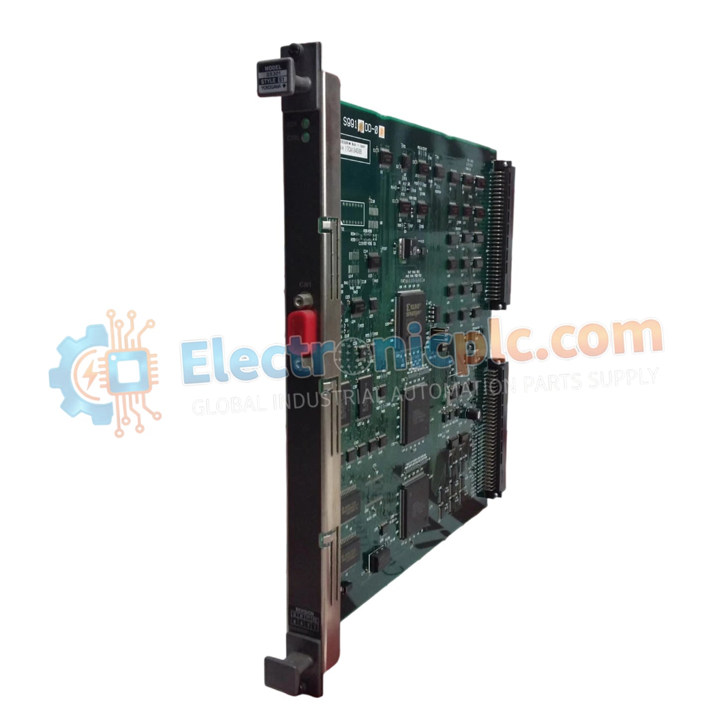
The YOKOGAWA SB301 S1, also cataloged as the SB301 Interface Module, operates as a dedicated hardware component for signal path adaptation within DCS process control platforms. This module provides direct physical/electrical execution for connecting field instrumentation to the system backplane, ensuring stable data transmission across control loops.
| Parameter | Specification |
| Model | SB301 S1 |
| Brand | YOKOGAWA |
| Origin | JAPAN |
| Weight | 0.3 kg |
| Dimensions | 2.5 cm x 26.0 cm x 24.8 cm |
| Operating Temp | -20 deg C to 70 deg C |
| Power Consumption | 5 W typical |
| Function | Interface Module |
The SB301 S1 is engineered to maintain high loop integrity, facilitating consistent 4-20 mA HART loop protocol signal transmission. It is configured to provide channel-to-channel isolation, preventing common-mode interference in multi-loop instrumentation cabinets. The hardware layout is optimized to reduce connection impedance, which minimizes signal drift during long-term operation in critical process control environments.
Q: Is the SB301 S1 module hot-swappable?
A: The module does not support hot-swapping. System power must be isolated before the module is removed from or inserted into the backplane to prevent potential electrical damage to the interface pins or the internal logic.
Q: Can this module be used in a redundant I/O configuration?
A: Yes, the SB301 S1 is compatible with redundant I/O architectures. Ensure that the corresponding software configuration is set to match the physical module placement to enable proper failover transition.
Verify that the DIN-rail or chassis mounting surface is clean and provides a solid electrical ground reference for the module housing.
Carefully align the interface module with the backplane connector before applying pressure. Do not force the module; ensure pins are seated correctly to avoid bending.
Tighten the module retention screws to the specified torque to maintain proper mechanical stability and electrical contact pressure.
Route field wiring away from high-voltage AC lines to minimize electromagnetic interference (EMI). Use shielded cables and ground the shield at a single, dedicated point to maintain signal accuracy.
After installation, verify the module status via the DCS configuration interface to ensure that the hardware is recognized and diagnostic checks have passed.


