My Cart
0 items
Genuine Automation Parts | Worldwide Express Delivery | 12-Month Warranty — [GET A QUOTE]

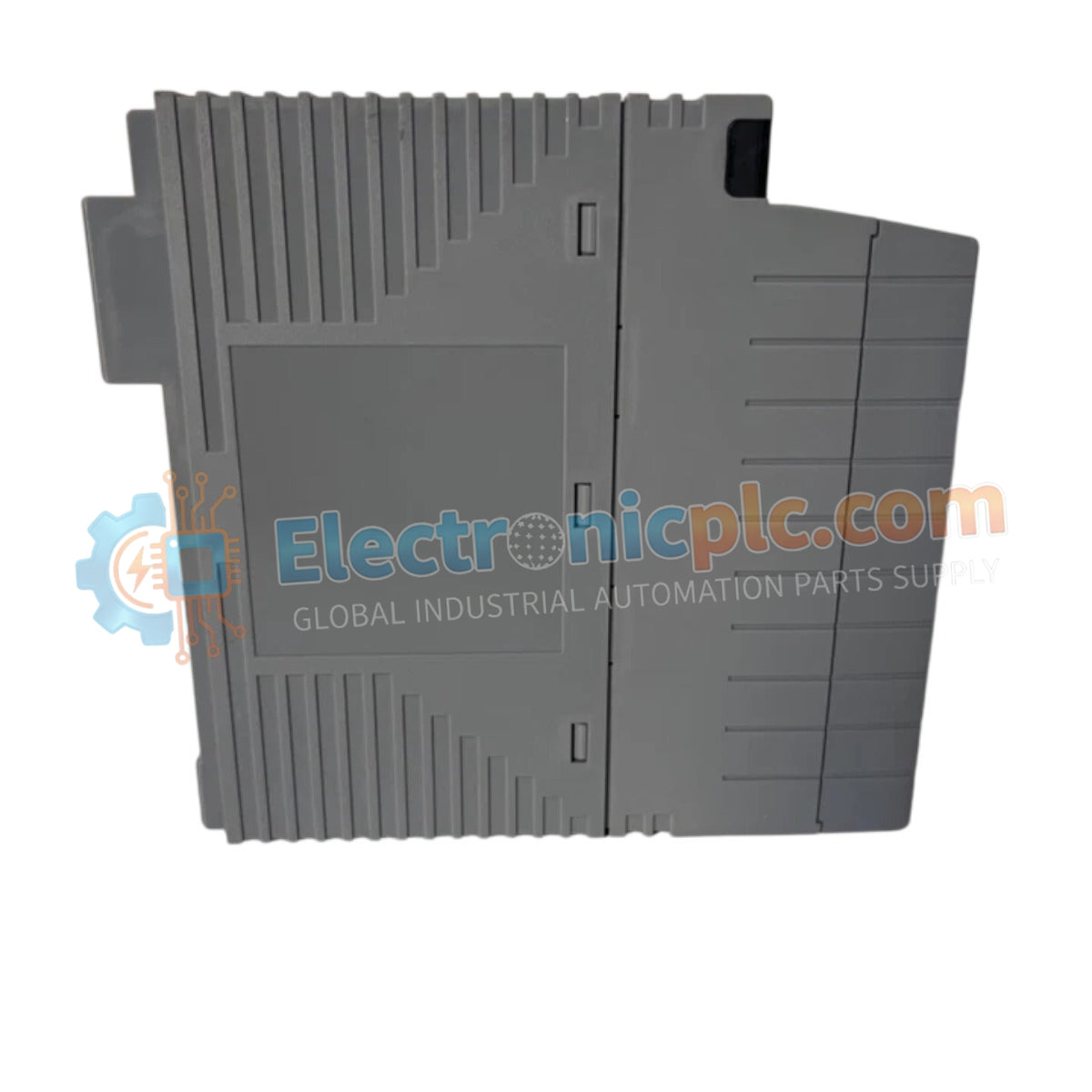
Configured for high-speed data transmission in DCS platforms, the YOKOGAWA SB401-53 (SB401-53 ESB Bus Interface Module) provides direct physical/electrical execution of slave-side communication protocols across ESB bus architectures.
Availability: Low stock: 99 left
Reliable Worldwide Delivery
30-Day Money-Back Guarantee
Need more details? Read our fullShipping PolicyandRefund Policy.


Configured for high-speed data transmission in DCS platforms, the YOKOGAWA SB401-53 (SB401-53 ESB Bus Interface Module) provides direct physical/electrical execution of slave-side communication protocols across ESB bus architectures.
| Parameter | Specification |
|---|---|
| Model | SB401-53 |
| Brand | YOKOGAWA |
| Origin | japan |
| Weight | 0.45 kg |
| Dimensions | Standard Rack-Mount Format |
| Operating Temp | Consult System Technical Manual |
| Power Consumption | Subject to Bus Load |
| Interface Type | ESB Bus Slave |
| Protection Class | Standard Type (Non-Explosive) |
| Coating | ISA Standard G3 |
The SB401-53 module acts as a slave node within the Yokogawa ESB bus architecture. To ensure robust performance within the DCS environment, the module employs channel-to-channel isolation techniques to prevent ground loops and electrical interference from propagating through the bus. Cold junction compensation (CJC) and precise signal conditioning are maintained for data integrity across the interface. The module is compliant with ISA Standard G3 environmental specifications, ensuring functional longevity in atmospheres where corrosive gases may be present.
Q: Does the SB401-53 support hot-swapping while the ESB bus is actively powered?
A: Hot-swapping the SB401-53 module during active bus operations is not recommended, as it may cause communication errors or node timeouts on the ESB network. Power cycles should be managed according to the host system station guidelines.
Q: Is this module compatible with non-ISA standard environments?
A: The module is designed for the ISA Standard G3 environment; however, it remains functionally compatible with standard control rack installations, provided ambient conditions do not exceed the specified operational limits of the host station.


