
My Cart
0 items
Genuine Automation Parts | Worldwide Express Delivery | 12-Month Warranty — [GET A QUOTE]

The YOKOGAWA SNB10D-415/CU2T, also cataloged as the SNB10D Safety Node Unit, operates as a dedicated hardware component for field signal interfacing within ProSafe-RS Safety Instrumented System (SIS) platforms.
Availability: In stock
Reliable Worldwide Delivery
30-Day Money-Back Guarantee
Need more details? Read our fullShipping PolicyandRefund Policy.
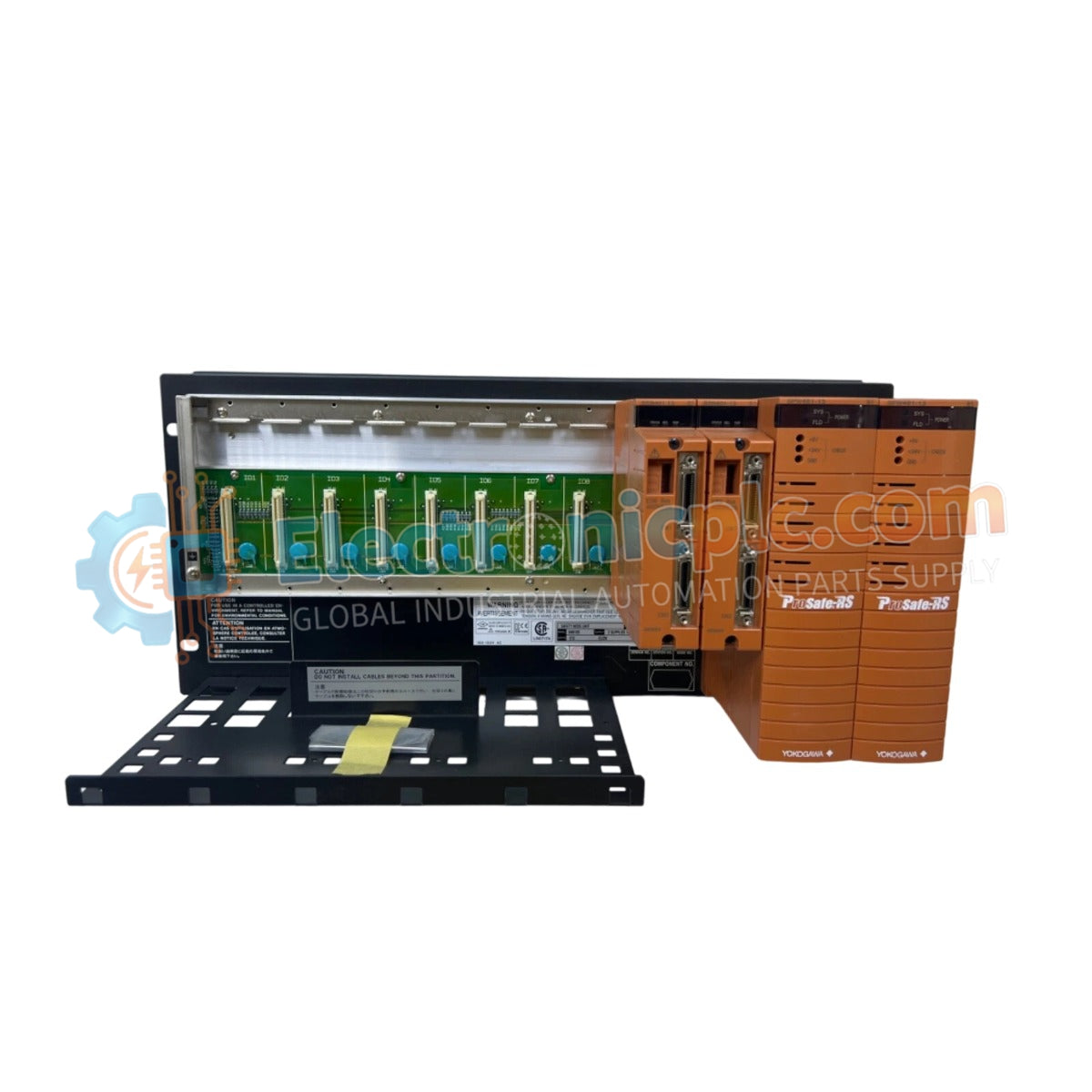

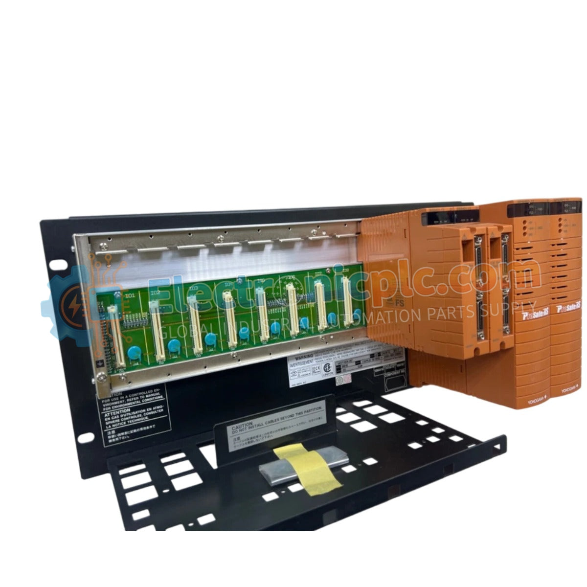
The YOKOGAWA SNB10D-415/CU2T, also cataloged as the SNB10D Safety Node Unit, operates as a dedicated hardware component for field signal interfacing within ProSafe-RS Safety Instrumented System (SIS) platforms.
| Parameter | Specification |
|---|---|
| Model | SNB10D-415/CU2T |
| Brand | YOKOGAWA |
| Origin | Japan |
| Weight | 5.9 kg |
| Dimensions | 482.6 mm x 221.5 mm x 205 mm |
| Operating Temp | 0 deg C to 50 deg C |
| Power Consumption | Not specified (SIS Power Bus) |
| Compatibility | ProSafe-RS SIS |
| Safety Standard | SIL3 compliant (IEC 61508) |
The SNB10D-415/CU2T is architected for SIL3 compliance, providing robust galvanic isolation between field instrumentation circuits and the internal safety control bus. This dual-redundant design ensures that the unit maintains continuous operation in the presence of single-point failures. In the event of a detected logic fault or communication loss with the safety processor, the node is engineered for immediate fail-safe state execution, driving connected valves and actuators to a predetermined safe position to mitigate process risks.
Q: Does the unit support hot-swapping of I/O modules during operation?
A: Yes, the SNB10D-415/CU2T supports hot-swapping of individual I/O modules. However, this must be performed in accordance with the site-specific safety procedures and under the condition that the safety controller has transitioned the affected loop to a permissive bypass or maintenance state.
Q: How is the dual-redundant power distribution managed within the rack?
A: The node unit utilizes redundant power input terminals that are diode-ORed to ensure continuous power delivery. The system monitors input voltage health and will trigger a diagnostic alarm via the safety controller if one power feed fails.


