
My Cart
0 items
Genuine Automation Parts | Worldwide Express Delivery | 12-Month Warranty — [GET A QUOTE]

Configured for high-speed signal conversion in ProSafe-RS safety systems, the Yokogawa SNT401-53/CU1N (SNT401 Optical ESB Bus Repeater Master Module) provides direct electrical-to-optical signal execution for extended communication distances.
Availability: In stock
Reliable Worldwide Delivery
30-Day Money-Back Guarantee
Need more details? Read our fullShipping PolicyandRefund Policy.


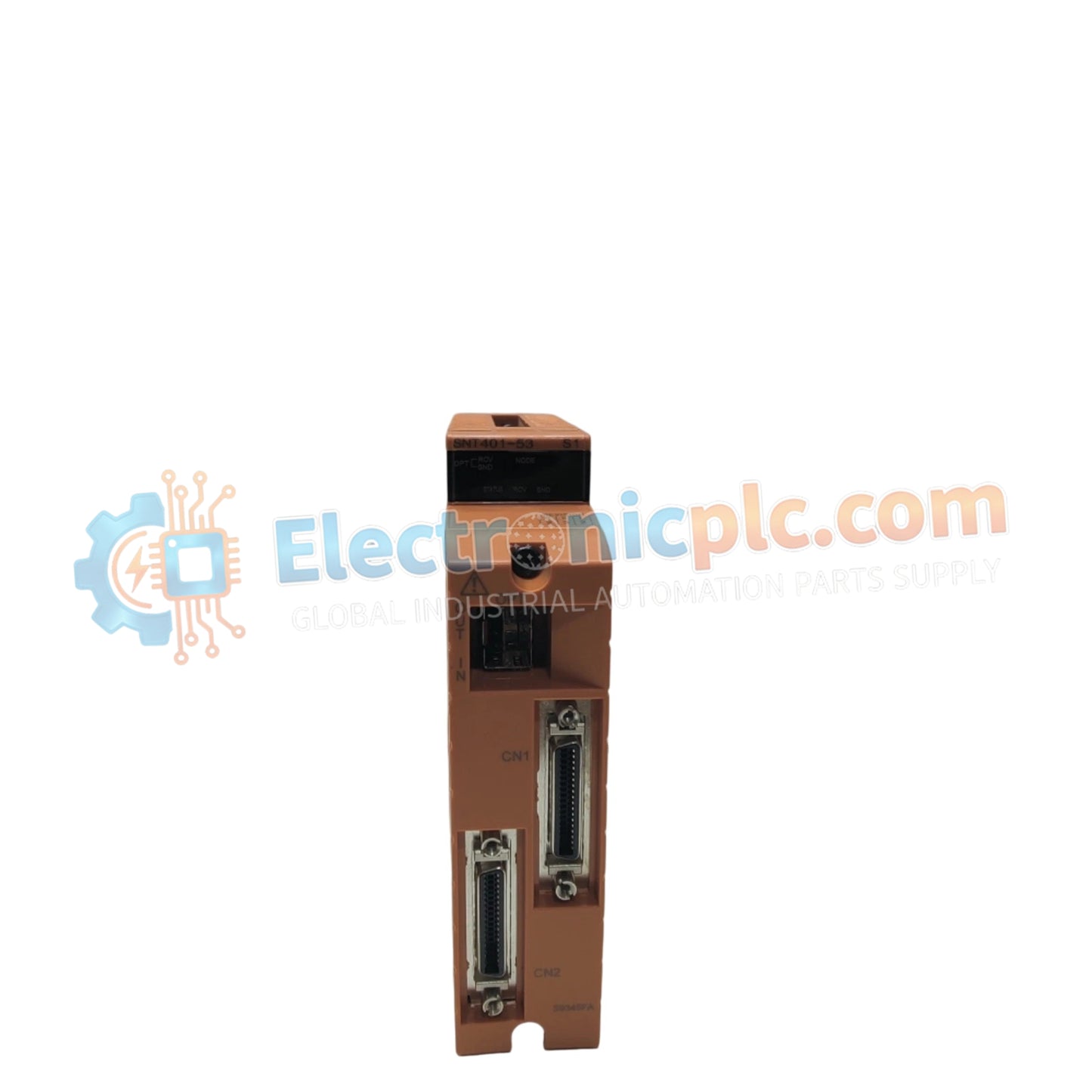
Configured for high-speed signal conversion in ProSafe-RS safety systems, the Yokogawa SNT401-53/CU1N (SNT401 Optical ESB Bus Repeater Master Module) provides direct electrical-to-optical signal execution for extended communication distances.
| Parameter | Specification |
|---|---|
| Model | SNT401-53/CU1N |
| Brand | Yokogawa |
| Origin | Japan |
| Weight | 0.2 kg |
| Dimensions | Standard Yokogawa Bus Module Form Factor |
| Operating Temp | -20 deg C to 70 deg C |
| Power Consumption | 220-240 VAC input requirement |
| Functionality | Electrical to Optical ESB signal conversion |
| Transmission Distance | Max 5 km (via ANT401 fiber optic cable) |
| Humidity | 10% to 90% (non-condensing) |
The SNT401-53/CU1N utilizes robust galvanic isolation to maintain signal integrity between the safety-critical electrical backplane and remote I/O nodes. Within the ProSafe-RS architecture, this module ensures fail-safe state execution by monitoring optical link continuity; any disruption in the fiber optic path triggers immediate bus status feedback to the master controller. The design facilitates deterministic data transmission, preventing signal degradation over the 5 km maximum span while maintaining the required SIL-rated isolation levels necessary for safety-critical network topologies.
Q: Does the SNT401-53/CU1N support hot-swapping during active operation?
A: No. Due to the nature of bus master modules and safety-critical system stability, the power supply must be disconnected and the system placed into a maintenance state before module removal or installation.
Q: Is the optical link monitoring capable of detecting partial signal attenuation?
A: The module is designed to monitor for link loss. While it provides transmission over 5 km, performance is contingent upon the use of specified ANT401 fiber optic cabling and proper termination to avoid excess signal loss that could trigger a bus fault.


