Skip to product information
1 of 3

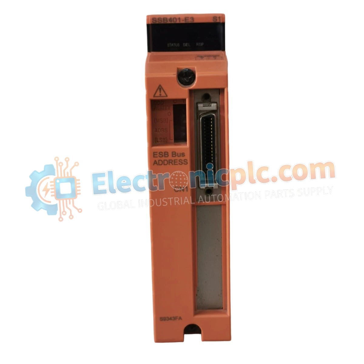
Yokogawa SSB401-53 + S9343FA ESB Bus Interface Module

Yokogawa SSB401-53 + S9343FA ESB Bus Interface Module

The Yokogawa SSB401-53 + S9343FA, also cataloged as the SSB401 ESB Bus Interface Module, operates as a dedicated hardware component for high-speed data aggregation and control bus management within CENTUM...

23 people are viewing this right now

AvailabilityIn stock

SKU: SSB401-53 + S9343FA
Vendor: Yokogawa

Shipping & Returns

Reliable Worldwide Delivery

  • Carriers: Shipped via DHL, FedEx, UPS, or USPS.
  • Dispatch: Orders processed in 1-2 business days and dispatched within 3-5 business days.
  • Tracking: Full tracking details provided via email upon shipment.

30-Day Money-Back Guarantee

  • Guarantee: 30-day return window for in-stock, factory-sealed products.
  • Condition: Items must be unopened, unused, and in original packaging.
  • Authenticity: We guarantee 100% original and authentic hardware.

Need more details? Read our fullShipping PolicyandRefund Policy.

Authenticity & Warranty

  • Genuine Guarantee: We supply only 100% original, brand-new, and factory-sealed industrial automation parts.
  • Full Coverage: Every component is backed by a 12-month comprehensive warranty from the date of purchase.
  • Traceability: All products come with original factory documentation and accessories for full industrial compliance.

Technical Support & Sourcing

  • Expert Assistance: Our technical team provides free consultation to help you verify compatibility for DCS and PLC systems.
  • Rare Part Sourcing: Specializing in obsolete and hard-to-find components from Allen-Bradley, Siemens, ABB, HIMA, and more.
  • Bulk Inquiries: Contact us at pambo@5gplc.com for volume pricing or customized project quotes.
View full product details

The Yokogawa SSB401-53 + S9343FA, also cataloged as the SSB401 ESB Bus Interface Module, operates as a dedicated hardware component for high-speed data aggregation and control bus management within CENTUM series distributed control systems.

Suffix Breakdown & Model Matrix

  • SSB401: Base model series for Extended System Bus (ESB) interface modules.
  • 53: Denotes standard configuration for local bus connectivity and signal path management.
  • S9343FA: Specific hardware revision and firmware bundle for backplane interface compatibility.

Hardware Specifications

Parameter Specification
Model SSB401-53 + S9343FA
Brand Yokogawa
Origin Japan
Weight 0.35 kg
Dimensions Standard DCS Module Form Factor
Operating Temp -20 deg C to 60 deg C
Power Consumption 24 VDC nominal
Interface Type ESB (Extended System Bus)
Compliance IEC, CE, RoHS

Process Control and Network Integrity

The SSB401-53 module provides the physical layer interface required to extend the DCS system bus, allowing for the connection of remote I/O nodes to the primary control station. To maintain the deterministic timing required for process regulation, the module utilizes high-speed differential signaling, which effectively mitigates noise and data collision risks on the ESB. The architecture supports redundant bus configurations, ensuring that the control system maintains a fail-safe state execution if a primary bus link is interrupted. The integration of S9343FA revision logic enhances packet verification, ensuring that data integrity is maintained across the entire system bus topology.

Frequently Asked Questions

Q: Can the SSB401-53 be hot-swapped while the DCS is in operation?

A: Yes, provided the ESB interface is configured for redundancy. When the bus is operating in a duplexed mode, the SSB401-53 can be removed and replaced; however, the secondary bus must be verified as active prior to module extraction to avoid communication loss.

Q: How does the module handle signal degradation on long cable runs?

A: The SSB401-53 includes integrated signal conditioning to compensate for attenuation over standard ESB cable lengths. If communication errors persist, verify that cable shielding is properly grounded to the cabinet bus to prevent common-mode noise interference.

Field Installation Guidelines

  • Mounting: Secure the module onto the dedicated DCS DIN rail or panel slot. Ensure the backplane connectors are fully engaged to prevent intermittent signal loss due to vibration.
  • Wiring: Route ESB communication cables through low-voltage shielded conduits. Avoid running bus cables alongside AC power lines or variable frequency drive (VFD) output lines to minimize EMI.
  • Grounding: The module chassis must be bonded to the main cabinet ground reference. A high-quality ground connection is required to maintain the immunity of the differential signal drivers.
  • Environmental: Keep the cabinet environment free of excessive humidity or conductive particulates, as these can bridge contacts and lead to short-circuit conditions on the bus interface.