Skip to product information
1 of 3

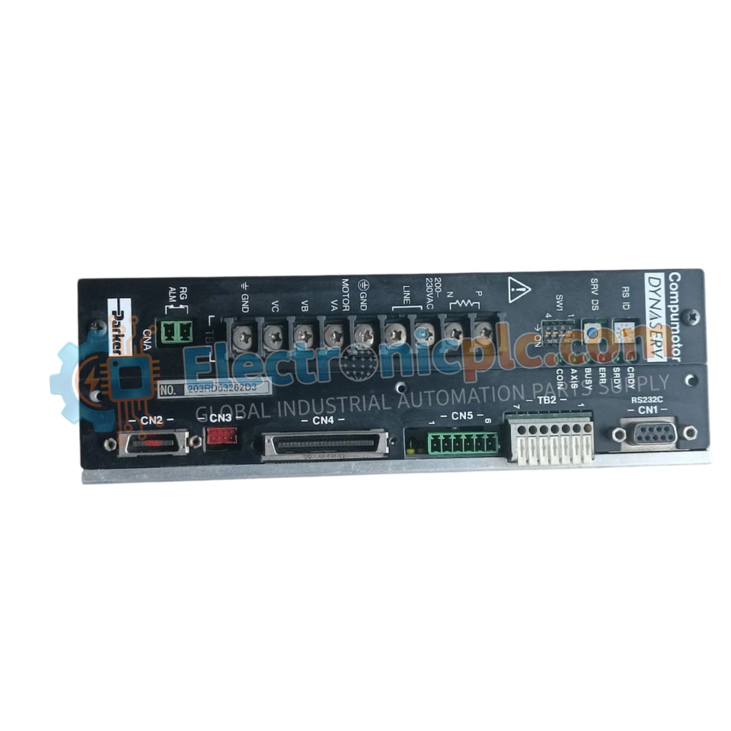
YOKOGAWA UR1015C6BB-2XN*C Servo Drive

YOKOGAWA UR1015C6BB-2XN*C Servo Drive

Configured for precision motion control in industrial automation networks, the YOKOGAWA UR1015C6BB-2XN*C (UR1015C6BB-2XN*C Servo Drive) provides direct electrical execution of motor velocity and position commands. The drive serves as a...

25 people are viewing this right now

AvailabilityIn stock

SKU: UR1015C6BB-2XN*C
Vendor: Yokogawa
Category: Servo Drive
Related Series:

Shipping & Returns

Reliable Worldwide Delivery

  • Carriers: Shipped via DHL, FedEx, UPS, or USPS.
  • Dispatch: Orders processed in 1-2 business days and dispatched within 3-5 business days.
  • Tracking: Full tracking details provided via email upon shipment.

30-Day Money-Back Guarantee

  • Guarantee: 30-day return window for in-stock, factory-sealed products.
  • Condition: Items must be unopened, unused, and in original packaging.
  • Authenticity: We guarantee 100% original and authentic hardware.

Need more details? Read our fullShipping PolicyandRefund Policy.

Authenticity & Warranty

  • Genuine Guarantee: We supply only 100% original, brand-new, and factory-sealed industrial automation parts.
  • Full Coverage: Every component is backed by a 12-month comprehensive warranty from the date of purchase.
  • Traceability: All products come with original factory documentation and accessories for full industrial compliance.

Technical Support & Sourcing

  • Expert Assistance: Our technical team provides free consultation to help you verify compatibility for DCS and PLC systems.
  • Rare Part Sourcing: Specializing in obsolete and hard-to-find components from Allen-Bradley, Siemens, ABB, HIMA, and more.
  • Bulk Inquiries: Contact us at pambo@5gplc.com for volume pricing or customized project quotes.
View full product details

Configured for precision motion control in industrial automation networks, the YOKOGAWA UR1015C6BB-2XN*C (UR1015C6BB-2XN*C Servo Drive) provides direct electrical execution of motor velocity and position commands. The drive serves as a primary interface for actuator loop feedback response, utilizing high-speed processing to modulate power output and maintain synchronization across multi-axis platforms.

Suffix Breakdown & Model Matrix

  • UR1015: Base model designation for the servo drive unit with 10-15 amperage capacity.
  • C6: Control loop revision level for high-frequency feedback processing.
  • BB: Interface and communication module configuration.
  • -2XN*C: Specific firmware version and regional assembly code for industrial integration.

Hardware Specifications

Parameter Specification
Model UR1015C6BB-2XN*C
Brand YOKOGAWA
Origin japn
Weight 2kg
Dimensions 2.2 cm x 12.4 cm x 12.6 cm
Operating Temp 0 to 50 deg C
Power Consumption 150 W (nominal)
Control Type Servo motion control
Output Capacity 10-15 A peak current

Thermal Heat Sink Dissipation Profiles

The UR1015C6BB-2XN*C is engineered with integrated thermal heat sink dissipation profiles optimized for continuous high-torque operation. The drive utilizes active thermal monitoring to adjust internal switching frequencies based on internal temperatures, preventing thermal saturation of the power transistors. This design ensures that the actuator loop feedback response remains stable despite fluctuations in ambient environmental conditions. The drive’s power circuitry includes harmonic distortion suppression to maintain motor efficiency and minimize EMI propagation within the control cabinet.

Frequently Asked Questions

Q: Does this drive support hot-swapping for maintenance?

A: No. Due to the high capacitance of the internal DC bus, the drive must be powered down and allowed to discharge for at least 5 minutes before physical removal from the backplane.

Q: Is this drive compatible with firmware-based vector control upgrades?

A: Yes. The drive supports flash-based firmware updates for optimized control algorithms. Compatibility should be verified against the host motion controller's communication protocol before initiating any firmware load.

Field Installation Guidelines

  1. Ensure the control cabinet provides adequate clearance for vertical airflow through the heat sink fins; maintain at least 10 cm of space above and below the unit.
  2. Verify the input voltage matches the drive requirements before powering the unit to prevent primary stage damage.
  3. Use shielded motor cables and route them separately from low-voltage I/O and communication cables to minimize signal crosstalk.
  4. Bond the drive chassis ground terminal to a low-impedance common ground point using a braided copper strap for effective high-frequency noise suppression.
  5. Confirm that the motor feedback connector (encoder/resolver) is fully seated and locked to avoid intermittent motion faults during high-speed operation.