
My Cart
0 items
Genuine Automation Parts | Worldwide Express Delivery | 12-Month Warranty — [GET A QUOTE]

Configured for precise process monitoring and safety interlocks, the YOKOGAWA UT150L (UT150L Limit Controller) provides direct physical/electrical execution. This hardware component functions as a 1/16 DIN limit controller, utilizing universal...
Availability: In stock
Reliable Worldwide Delivery
30-Day Money-Back Guarantee
Need more details? Read our fullShipping PolicyandRefund Policy.


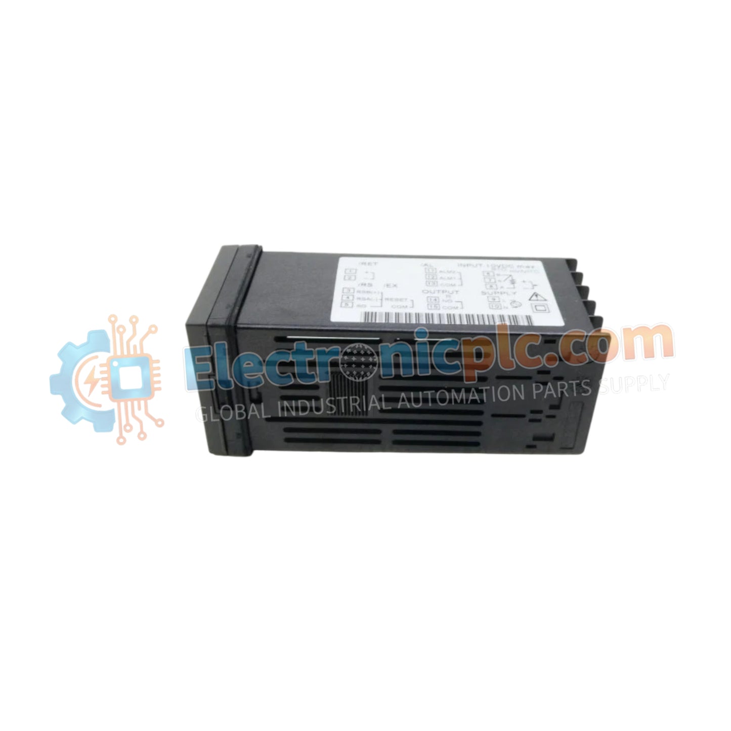
Configured for precise process monitoring and safety interlocks, the YOKOGAWA UT150L (UT150L Limit Controller) provides direct physical/electrical execution. This hardware component functions as a 1/16 DIN limit controller, utilizing universal input stages to monitor variables such as temperature, pressure, or flow, and triggering SPDT relay outputs upon threshold violations.
| Parameter | Specification |
|---|---|
| Model | UT150L |
| Brand | YOKOGAWA |
| Origin | JAPAN |
| Weight | 1.2 kg |
| Dimensions | 48 mm x 48 mm (1/16 DIN) |
| Operating Temp | -10 to 50 deg C |
| Power Consumption | 10 VA (Typical) |
| Display | Dual 4-digit LED |
| Sampling Period | 250 ms |
| Control Output | SPDT Relay (3 A @ 250 VAC) |
The UT150L features a versatile input architecture capable of processing various signals, including Type K, J, T, E, R, S, B, N, W, and PL2 thermocouples, as well as Pt100/JPt100 RTD sensors. For voltage and current loops, it accepts 0-1 V, 0-5 V, 1-5 V, or 0-10 V inputs directly, and 4-20 mA signals via external shunt resistors. The device integrates PID control with overshoot suppression and auto-tuning capabilities, ensuring that process stability is maintained even in dynamic industrial environments where variable fluctuation is frequent.
Q: Does the UT150L provide galvanic isolation between the input signal and the relay output?
A: Yes, the controller maintains electrical isolation between the sensor input stage and the SPDT relay output to protect the internal processing circuitry from common-mode transients on the field side.
Q: Can the 4-20 mA current input be connected directly to the module input terminals?
A: No, the 4-20 mA signal must be converted to a voltage signal using a precision external shunt resistor prior to reaching the UT150L input terminals to ensure proper measurement scaling.


