Skip to product information
1 of 3

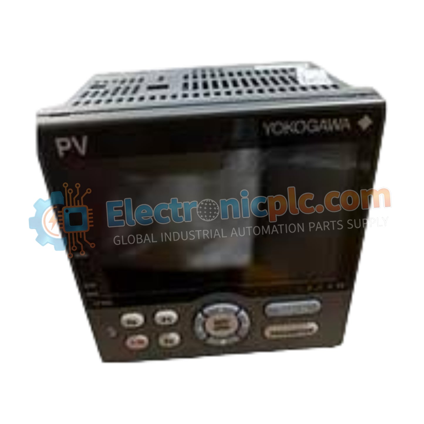
Yokogawa UT35A-100-10-00 Digital Indicating Controller

Yokogawa UT35A-100-10-00 Digital Indicating Controller

The Yokogawa UT35A-100-10-00, also cataloged as the UT35A Digital Indicating Controller, operates as a dedicated hardware component for multi-loop process regulation and setpoint management within industrial control systems.

Suffix Breakdown...

22 people are viewing this right now

AvailabilityIn stock

SKU: UT35A-100-10-00
Vendor: Yokogawa

Shipping & Returns

Reliable Worldwide Delivery

  • Carriers: Shipped via DHL, FedEx, UPS, or USPS.
  • Dispatch: Orders processed in 1-2 business days and dispatched within 3-5 business days.
  • Tracking: Full tracking details provided via email upon shipment.

30-Day Money-Back Guarantee

  • Guarantee: 30-day return window for in-stock, factory-sealed products.
  • Condition: Items must be unopened, unused, and in original packaging.
  • Authenticity: We guarantee 100% original and authentic hardware.

Need more details? Read our fullShipping PolicyandRefund Policy.

Authenticity & Warranty

  • Genuine Guarantee: We supply only 100% original, brand-new, and factory-sealed industrial automation parts.
  • Full Coverage: Every component is backed by a 12-month comprehensive warranty from the date of purchase.
  • Traceability: All products come with original factory documentation and accessories for full industrial compliance.

Technical Support & Sourcing

  • Expert Assistance: Our technical team provides free consultation to help you verify compatibility for DCS and PLC systems.
  • Rare Part Sourcing: Specializing in obsolete and hard-to-find components from Allen-Bradley, Siemens, ABB, HIMA, and more.
  • Bulk Inquiries: Contact us at pambo@5gplc.com for volume pricing or customized project quotes.
View full product details

The Yokogawa UT35A-100-10-00, also cataloged as the UT35A Digital Indicating Controller, operates as a dedicated hardware component for multi-loop process regulation and setpoint management within industrial control systems.

Suffix Breakdown & Model Matrix

  • UT35A: Base model series for digital indicating controllers (1/4 DIN size).
  • 100: Denotes standard single-loop control configuration with primary input and output sets.
  • 10: Indicates power supply range (100-240 VAC) and basic terminal structure.
  • 00: Represents standard display options and factory-default firmware settings.

Hardware Specifications

Parameter Specification
Model UT35A-100-10-00
Brand Yokogawa
Origin Japan
Weight  0.4 kg
Dimensions 96 mm x 96 mm x 100 mm
Operating Temp 0 deg C to 50 deg C
Power Consumption 15 VA maximum
Display 14-segment color LCD
Control Modes PID, ON/OFF, Heating/Cooling, Sampling PI
Communication Ethernet and RS-485

Process Control and Loop Integrity

The UT35A-100-10-00 integrates into DCS and PLC frameworks, maintaining signal precision through support for the 4-20 mA HART loop protocol. To prevent signal degradation in noisy industrial environments, the controller features robust channel-to-channel isolation on its analog interfaces. When utilizing thermocouple or RTD inputs, the controller automatically performs cold junction compensation (CJC) to eliminate ambient temperature-induced measurement errors, ensuring that the process variable tracked by the PID algorithm remains within strict operational tolerances.

Frequently Asked Questions

Q: Can the UT35A-100-10-00 perform hot-swapping of the control module?

A: No. The unit is designed for permanent panel mounting. Power must be fully disconnected and the terminal block removed from the rear before attempting to slide the controller chassis out of the panel housing.

Q: How does the heater break alarm function with the standard output configuration?

A: The alarm requires an external Current Transformer (CT) connected to the specified digital input. The controller compares the measured load current against the setpoint; if the current drops below the defined threshold, an alarm output is triggered.

Field Installation Guidelines

  • Mounting: Ensure the panel cutout is precisely 92 mm x 92 mm. Use the provided brackets to secure the unit, tightening evenly to ensure the gasket forms a tight seal against the panel face.
  • Wiring: Keep signal leads separate from AC power lines by at least 150 mm. Use shielded twisted-pair cabling for RS-485 and Ethernet connections to maintain signal integrity.
  • Grounding: Connect the functional earth terminal to a high-quality, low-impedance ground point to minimize common-mode noise.
  • Thermal Management: Ensure 50 mm of clearance above and below the controller to facilitate convective airflow, preventing internal components from exceeding the 50 deg C operating limit.