Skip to product information
1 of 2

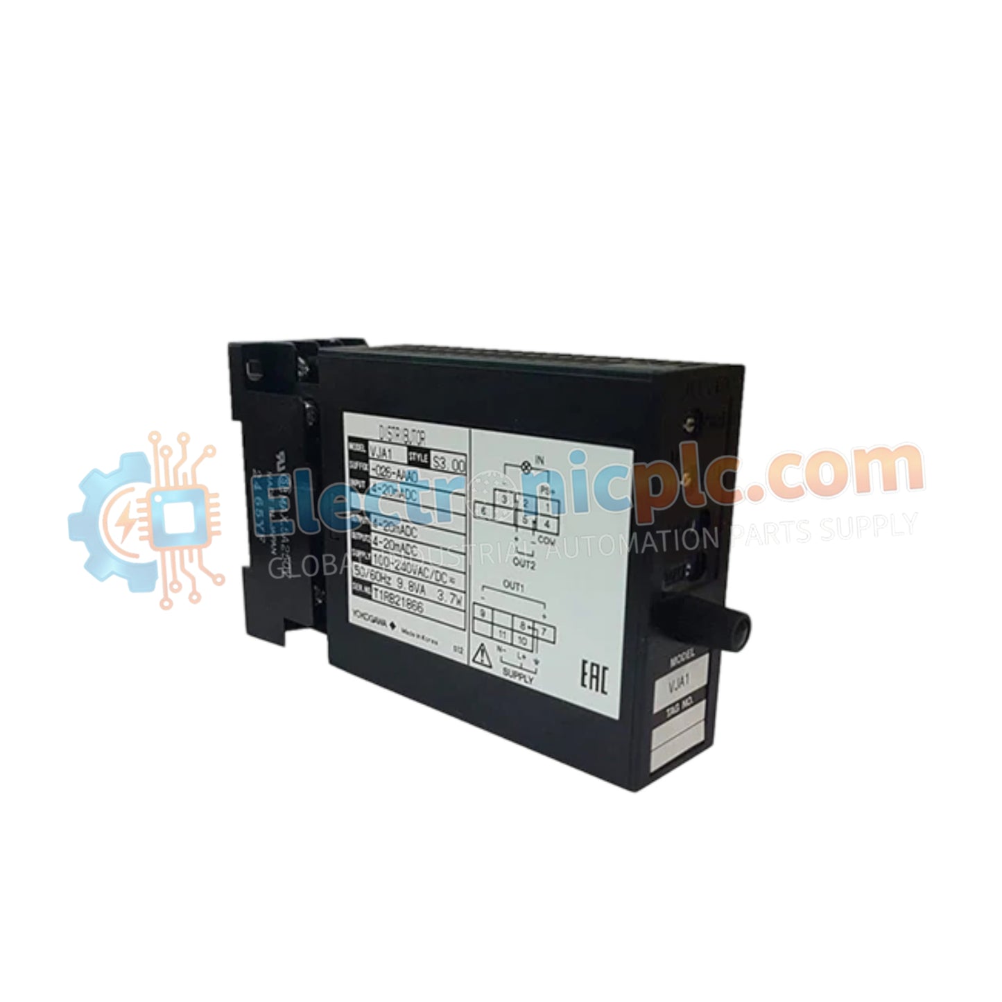
YOKOGAWA VJSS-L17-AAN0 Signal Isolator

YOKOGAWA VJSS-L17-AAN0 Signal Isolator

Configured for precision signal conditioning in industrial control platforms, the YOKOGAWA VJSS-L17-AAN0 (VJSS-L17-AAN0 Signal Isolator) provides direct physical signal isolation and conversion for VJ series instrumentation loops.

Suffix Breakdown &...

24 people are viewing this right now

AvailabilityIn stock

SKU: VJSS-L17-AAN0
Vendor: Yokogawa
Category: Signal Isolator
Related Series:

Shipping & Returns

Reliable Worldwide Delivery

  • Carriers: Shipped via DHL, FedEx, UPS, or USPS.
  • Dispatch: Orders processed in 1-2 business days and dispatched within 3-5 business days.
  • Tracking: Full tracking details provided via email upon shipment.

30-Day Money-Back Guarantee

  • Guarantee: 30-day return window for in-stock, factory-sealed products.
  • Condition: Items must be unopened, unused, and in original packaging.
  • Authenticity: We guarantee 100% original and authentic hardware.

Need more details? Read our fullShipping PolicyandRefund Policy.

Authenticity & Warranty

  • Genuine Guarantee: We supply only 100% original, brand-new, and factory-sealed industrial automation parts.
  • Full Coverage: Every component is backed by a 12-month comprehensive warranty from the date of purchase.
  • Traceability: All products come with original factory documentation and accessories for full industrial compliance.

Technical Support & Sourcing

  • Expert Assistance: Our technical team provides free consultation to help you verify compatibility for DCS and PLC systems.
  • Rare Part Sourcing: Specializing in obsolete and hard-to-find components from Allen-Bradley, Siemens, ABB, HIMA, and more.
  • Bulk Inquiries: Contact us at pambo@5gplc.com for volume pricing or customized project quotes.
View full product details

Configured for precision signal conditioning in industrial control platforms, the YOKOGAWA VJSS-L17-AAN0 (VJSS-L17-AAN0 Signal Isolator) provides direct physical signal isolation and conversion for VJ series instrumentation loops.

Suffix Breakdown & Model Matrix

  • VJSS: Base model for VJ series plug-in signal isolator.
  • -L: Specifies the power supply range.
  • 17: Designates input and output signal range configurations.
  • -AAN0: Defines housing, terminal, and certification options for standard control applications.

Hardware Specifications

Parameter Specification
Model VJSS-L17-AAN0
Brand YOKOGAWA
Origin Japan
Weight  0.15 kg
Dimensions Plug-in module form factor
Operating Temp -10 to 55 deg C
Power Consumption 24 VDC nominal
Input Signal Standard process loop input
Output Signal Isolated process loop output
Isolation Input, output, and power supply

Process Control Signal Conditioning

The VJSS-L17-AAN0 employs advanced circuitry to ensure electrical isolation between the field input and the instrumentation system output. This architecture is critical for managing ground potential differences and preventing signal noise in large-scale process control networks. The unit maintains strict signal linearity, ensuring that 4-20 mA HART loop protocol data is passed through the isolator with minimal attenuation, thus preserving the accuracy of the process variable before it reaches the control processor or recording device.

Frequently Asked Questions

Q: Is this isolator compatible with hazardous area installations?

A: The VJSS-L17-AAN0 is designed for standard industrial environments. Compatibility with intrinsic safety (Ex i) requirements is dependent on specific suffix codes not present in this model; refer to the product label for certification verification.

Q: How should the module be configured for input range calibration?

A: The VJSS series features field-adjustable zero and span potentiometers accessible through the front panel, allowing for precise calibration without removing the module from the mounting base.

Field Installation Guidelines

  • Ensure the plug-in base is securely mounted to a standard DIN-rail to maintain mechanical stability and proper electrical contact.
  • Verify that the input and output signal polarity matches the wiring diagram provided on the side casing to prevent reverse current faults.
  • Utilize shielded, twisted-pair cabling for signal runs to mitigate electromagnetic interference (EMI) and cross-talk from nearby power circuits.
  • Monitor the power supply voltage to ensure it remains within the specified nominal range to prevent signal drift or internal overheating.
  • Keep the module away from high-vibration sources to preserve the integrity of the board-to-socket interface.