My Cart
0 items
Genuine Automation Parts | Worldwide Express Delivery | 12-Month Warranty — [GET A QUOTE]

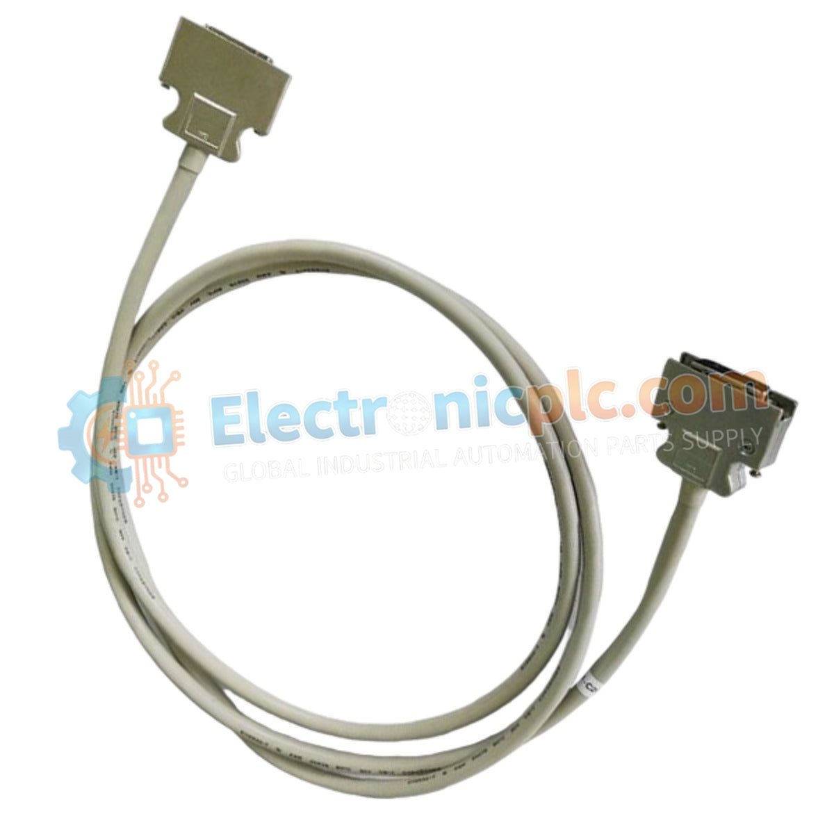
Configured for high-speed network communication within industrial control systems, the Yokogawa YCB111-M025 (YCB111-M025 Coaxial Bus Cable) provides direct physical signal transmission for V net, ER, ESB, and RIO bus platforms.
...Availability: In stock
Reliable Worldwide Delivery
30-Day Money-Back Guarantee
Need more details? Read our fullShipping PolicyandRefund Policy.


Configured for high-speed network communication within industrial control systems, the Yokogawa YCB111-M025 (YCB111-M025 Coaxial Bus Cable) provides direct physical signal transmission for V net, ER, ESB, and RIO bus platforms.
| Model | Component Description |
|---|---|
| YCB111 | Base Coaxial Bus Cable series (Thick Ethernet) |
| -M025 | Cable length configuration (25 meters) |
| Parameter | Specification |
|---|---|
| Model | YCB111-M025 |
| Brand | Yokogawa |
| Origin | japan |
| Weight | 0.75kg |
| Dimensions | 25 meters length |
| Operating Temp | -20 deg C to +70 deg C |
| Power Consumption | Passive component |
| Communication Standard | 10BASE-5 (Thick Ethernet) |
| Connector Type | Solderless for M4 screw terminals |
| Shielding | High-density EMI/RFI braid |
The YCB111-M025 is engineered to maintain low-latency data flow within Yokogawa CENTUM VP and ProSafe-RS architectures. The cable utilizes intrinsic safety (Ex i) barrier-compatible construction where required and provides DIN-rail mounting stability when used in conjunction with secondary conduit routing. The assembly offers surge voltage protection limits necessary for maintaining communication link stability in high-EMI industrial zones. By adhering to 10BASE-5 standards, the cable ensures protocol conversion latencies are kept within the precise millisecond tolerances required for deterministic V net communication.
Q: Can the YCB111-M025 be used in areas with high vibration?
A: Yes. The industrial-grade flame-retardant jacket and robust shielding allow for installation in high-vibration areas, provided the cable is securely fastened at regular intervals to prevent mechanical fatigue at the termination points.
Q: What is the minimum bending radius for this cable during installation?
A: The minimum bending radius for permanent installation is 100 mm. Exceeding this limit by creating tighter bends will cause deformation of the coaxial core, leading to impedance mismatch and signal reflection.


