
My Cart
0 items
Genuine Automation Parts | Worldwide Express Delivery | 12-Month Warranty — [GET A QUOTE]

The YOKOGAWA YPH105E (YT204001-FC PC BOARD) operates as a critical internal hardware component designed for signal routing, logic execution, and system-level interface management within Yokogawa industrial instrumentation. This printed circuit board assembly is...
Availability: In stock
Reliable Worldwide Delivery
30-Day Money-Back Guarantee
Need more details? Read our fullShipping PolicyandRefund Policy.


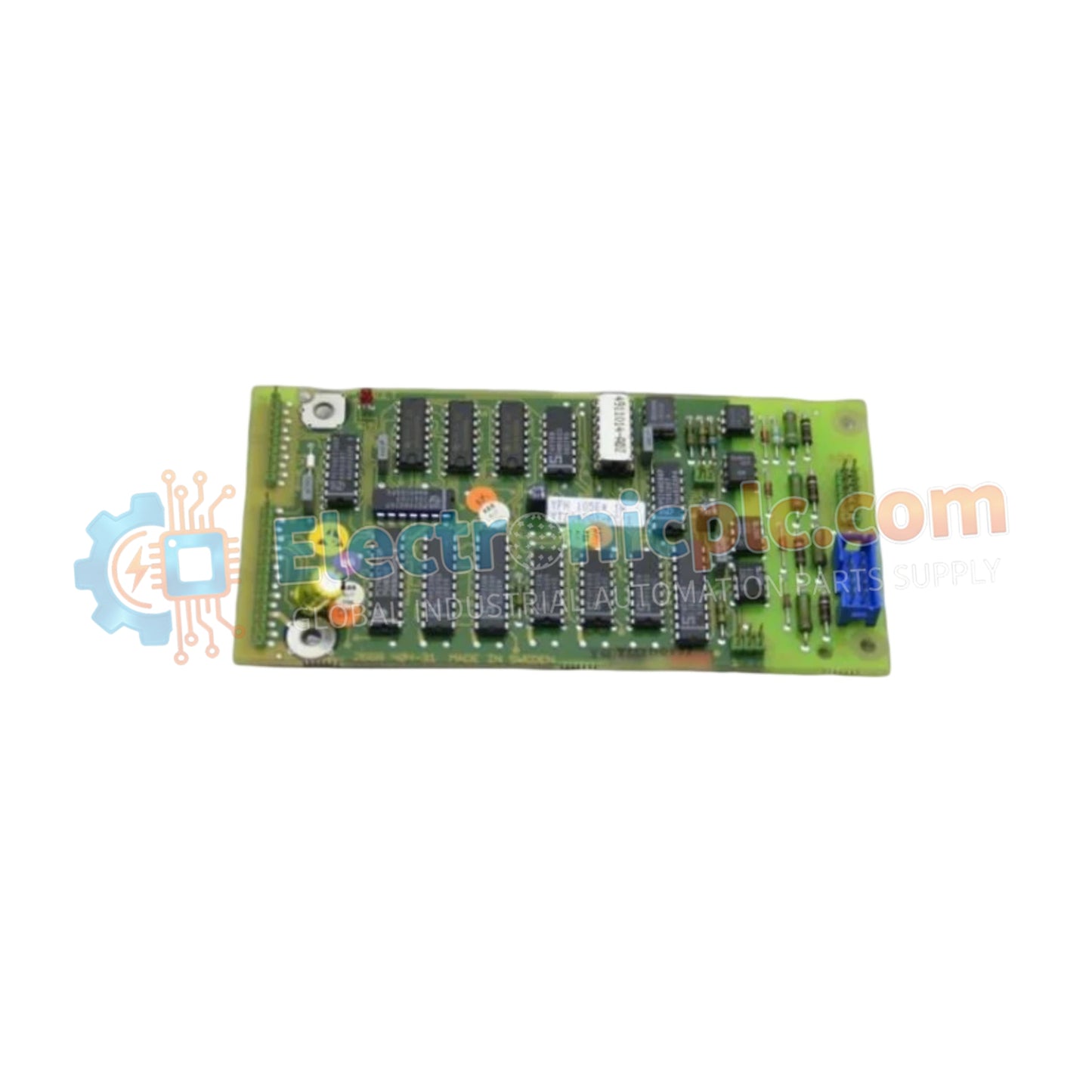
The YOKOGAWA YPH105E (YT204001-FC PC BOARD) operates as a critical internal hardware component designed for signal routing, logic execution, and system-level interface management within Yokogawa industrial instrumentation. This printed circuit board assembly is engineered to facilitate the precise electronic handshaking required between field-instrumentation sensors and the primary control processing units.
| Parameter | Specification |
| Model | YPH105E |
| Brand | YOKOGAWA |
| Origin | Japan |
| Weight | 0.3 kg |
| Dimensions | 7.6 cm x 5.1 cm x 12.7 cm |
| Operating Temp | Industrial Standard |
| Component Type | PC Board Assembly |
As a fundamental component of the instrumentation chassis, the YPH105E supports high-speed signal transit and data integrity. Its circuit design is optimized to maintain low impedance and high common-mode noise rejection, ensuring that sensitive analog or digital signals from the field are not corrupted during the processing stages. By acting as the central processing logic bridge, the board ensures that the controller can translate field inputs into actionable control logic with minimal latency.
Q: Is this board compatible with different Yokogawa instrumentation models?
A: The YPH105E is model-specific. Compatibility depends on the exact revision of the instrumentation host. You should verify the part number (YT204001-FC) against the existing board in your equipment to ensure exact electrical and mechanical matching.
Q: What precautions should be taken during maintenance or replacement?
A: Because this board contains sensitive integrated circuits, you must strictly follow Electrostatic Discharge (ESD) protocols. Use a grounded wrist strap and keep the board in an anti-static bag until the moment of installation. Never touch the gold-plated edge connectors with bare fingers, as skin oils can cause corrosion over time.
Power Isolation: Always isolate the power supply to the instrumentation rack before attempting to access or remove internal modules to prevent accidental short-circuits.
Alignment: Ensure the board is perfectly aligned with the backplane guides before insertion. Do not force the board; it should slide smoothly into the connector.
Seating: Firmly press the board until the edge connector is fully seated. Improper seating can result in intermittent signal faults or system instability.
Verification: After installation, perform a power-on self-test (POST) via the instrument's diagnostic interface to ensure the board is initialized correctly and reporting no hardware status errors.
Fastening: Secure the board using any associated retention screws to ensure it remains vibration-resistant in heavy-duty industrial environments.


